Check the kit, BOM and STL files
Identify your edition before assembling. Both use Arduino Uno Q and 15 serial servos; the full kit adds audio, a camera and ToF modules. Compare the delivered parts with the matching bill of materials rather than treating the two packages as identical.
The basic kit requires a separately 3D-printed shell. Use the hardware repository’s STL files and assembly documentation for your revision. Published design files do not mean every printed part or accessory is included in a seller’s package.
Open the setup console
Deploy the matching runtime following its upstream instructions, then run the Microduck Robot application in Arduino App Lab. Wait for a successful start before opening the control interface.
- Find the robot’s actual IP address.
- Open http://deviceIP:9527/ in your computer browser, replacing deviceIP with that address.
- Confirm the control page loads before proceeding to Servo setup. An IP address shown in an example is not your robot’s assigned address.
Set one servo ID at a time
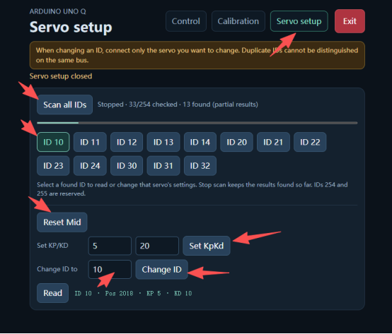
Connect only the servo being configured. New servos use default ID 1 in the documented procedure; duplicate IDs on a shared bus cause errors. Obtain each target ID from the version-specific assembly instructions, not from the screenshot’s example ID 10.
- In Servo setup, click Scan all IDs and select ID 1 for a new servo.
- Click Reset Mid, then Set KpKd.
- Enter its assigned target ID in Change ID to, then click Change ID.
- Record the new ID and physical installation position before repeating the process for the next servo.
Assemble using the hardware instructions
After assigning all servo IDs, follow the hardware project’s illustrated assembly sequence and connect the cables as documented. Keep your ID-to-position record available so similar-looking servos are not interchanged.
This overview does not specify screw torque, connector pinouts or substitute wiring. Use the drawings and parts for your revision, and resolve any mismatch before applying the movement procedure. A parts list alone is not a wiring diagram.
Calibrate each joint’s zero position
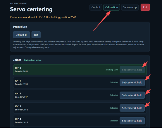
Power on and run the application in Arduino App Lab. Open Calibration from the control page. The documented calibration mode initially releases torque on all servos.
- Move one joint by hand to its reference zero position.
- Click that servo’s Set center & hold; it should hold the position you set.
- Repeat for every joint, checking the joint identity before each action.
Recognize the calibration pose
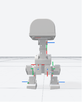
In the reference zero pose, the links are vertical or horizontal as shown in the upstream front and side views. This is a calibration reference, not the walking stance.
The robot not standing freely in this pose is expected. Do not change zero positions merely to make the calibration pose balance; compare the actual joint alignment with the revision’s reference illustrations.
Check standing before walking
After all joints are calibrated, return to Control and click Default pose. The robot should hold its default posture and be able to stand. If it does not, revisit the ID mapping, assembly and calibration before starting the walking policy.
- Once normal standing is confirmed, disconnect the USB Type-C cable as described upstream.
- Place the robot on the floor rather than an elevated surface.
- Click Walk / get up to load the walking and get-up policies, then use the joystick to control movement.
Troubleshoot by returning to the last confirmed step
These are diagnostic checkpoints, not confirmed diagnoses. Keep the relevant runtime version, servo ID record and observed behavior when consulting the upstream project. If the procedure or screen differs, use the corresponding upstream version rather than improvising IDs or control values.
Scroll sideways to compare all columns.
| Observed sign | Checkpoint |
|---|---|
| Control page does not load | Confirm the application started and check the device IP and port 9527. |
| Servo scan or selection is inconsistent | Return to one servo at a time and check for duplicate IDs. |
| Wrong joint moves or the default stance is distorted | Compare the ID-to-position mapping and zero alignment with the hardware instructions. |
| Calibration pose cannot stand | Distinguish the reference zero pose from Default pose before changing calibration. |